Crystallography and metallography of carbides in high alloy steels
- a Senior Materials Specialist, The Timken Co., Canton, Ohio, United States
- b General Manager, EMV Technologies, Bethlehem, Pennsylvania, United States
- Received 6 June 2007
- Accepted 2 July 2007
- Available online 16 July 2007
Abstract
The carbides in high carbon, high chromium bearing steels, high chromium carburizing steels, newly developed easily carburizable low carbon, low chromium high speed steels and M62 high speed steel fabricated by powder metal processing were studied. The particular steels evaluated include 440C, BG42. M50-Nil, CHS1, CHS50, Pyrowear 675®, CSS-42L™ and M62. The morphology and structure of the carbides were evaluated by means of metallography, X-ray diffraction and electron beam backscattered diffraction. The combination of these three techniques has provided new insight into how different carbide morphologies form during processing and the carbide structures that can be expected to be present in components fabricated from these steels by various types of heat treating.
Keywords
- Carbides;
- High speed steels;
- Carburizable bearing steels;
- Crystallography;
- X-ray diffraction;
- Electron beam backscattered diffraction
1. Introduction
Heat treated steels have been used for manufacturing antifriction bearings almost since their invention. Steels are used for these types of applications, because in the hardened and tempered condition the material has a very high yield strength and good resistance to wear and debris. Plain carbon steel containing over 0.80% carbon is an inexpensive material that can be used for low cost commodity bearings. The material is hardened by first heating it into the austenite phase for a moderate length of time. After austenitizing, the steel is generally oil quenched, and the resulting brittle constituent termed martensite is formed. In the as-quenched condition martensite has a body centered tetragonal crystallographic structure and is supersaturated with carbon. Subsequent tempering at temperatures in the range of 500 °C improves the toughness of the steel. After tempering, the microstructure of the steel is composed of body centered cubic martensite and intermediate carbide originally reported to be Fe2C [1], then believed to be Fe20C9[2]. The carbide was reported to have a hexagonal structure and designated as ɛ carbide [3], and recently reported to be orthorhombic F2C [4]. The use of high austenitizing temperatures can often lead to high amounts of retained austenite in the quenched and tempered microstructures of bearing steels, Fig. 1. To minimize the amount of retained austenite, for hypereutectoid steels, intermediate austenitizing treatments between the A1 and Acm temperatures are used.
One of the first alloys developed for commercial use as a bearing material was 52100 steel. This alloy is primarily composed of 1% carbon and 1.5% chromium, Table 1. When austenitized at intermediate temperatures, quenched and tempered, the microstructure is found to primarily consist of tempered martensite and small spherical (Cr,Fe)3C carbides [5], Fig. 2. Generally the iron–chromium cementite is designated as M3C. In this and all similar examples to follow, the capital letter M refers to metallic elements that can form carbides. Typical carbide forming elements include, but are not limited to Cr, Fe, Mo, V, W, Nb, Ti and Zr.
Table 1.
Nominal bearing steel compositions
| Alloy | Element (wt.%)
|
|---|
| C | Mn | Cr | Mo | V | W | Co | Ni | Nb |
|---|
| 52100 | 1.00 | 0.35 | 1.5 | | | | | | |
| 4620 | 0.20 | 0.55 | | 0.25 | | | | 1.8 | |
| 440C | 1.00 | 1.00 | 17.0 | 0.75 | | | | | |
| BG 42 | 1.15 | | 14.0 | 4.0 | 1.2 | | | | |
| M50 | 0.80 | 0.35 | 4.0 | 4.25 | 1.00 | | | | |
| M 1 | 0.83 | 0.30 | 3.75 | 8.5 | 1.15 | 1.75 | | | |
| M 2 | 0.85 | | 4.2 | 5.1 | 1.85 | 6.3 | | | |
| M 62 | 1.30 | | 3.75 | 10.5 | 2.0 | 6.25 | | | |
| T 1 | 0.75 | | 4.1 | | 1.1 | 18.0 | | | |
| M50 Nil | 0.13 | 0.20 | 4.1 | 4.25 | 1.25 | | | 3.40 | |
| CHS 50 | 0.10 | 0.25 | 1.2 | 5.75 | 1.20 | | | 2.80 | 0.20 |
| CHS 1 | 0.28 | 0.25 | 1.5 | 9.0 | 1.25 | 1.00 | | 2.00 | 0.20 |
| P 675 | 0.07 | 0.65 | 13.0 | 1.8 | 0.6 | | 5.4 | 2.6 | |
| CSS 42L | 0.13 | | 14.0 | 4.75 | 0.6 | | 12.5 | 2.0 | |
- Full-size table
While 52100 steel is used in numerous bearing applications, this and all high carbon steels have one major deficiency; they have poor impact toughness.
To enhance fracture toughness, many bearings are manufactured by using carburizable alloy steels. One of the first carburizable alloy steels used for bearing manufacturing was 4620. In addition to the low carbon level of 0.20%, this steel contains approximately 0.55% Mn, 1.8% Ni and 0.25% Mo, Table 1. After carburizing at 950 °C and then heat treating at an intermediate temperature of approximately 830 °C, the near surface microstructure of carburized components consists of tempered martensite, some retained austenite and small round alloy carbides, Fig. 1. Early studies on the carbides in the high carbon surface region of carburized bearings manufactured from this alloy were performed by electrolytically extracting the carbides from the steel matrix and analyzing them by X-ray diffraction. This work revealed the carbides to be face centered cubic (FCC) with a unit cell dimension of approximately 1.06 nm [6] and [7]. Chemically, these carbides were determined to be M23C6.
One disadvantage possessed by these alloy steels was that they displayed poor corrosion resistance. In order to passivate steel, it has been shown that a minimum chromium content of 12% by weight is necessary. Using this principle, a 1% carbon bearing steel containing 17% chromium and up to 0.75% molybdenum, named 440C, was developed. Due to the higher alloy content of this steel when compared to 52100 or a standard carburizing grade many more primary carbides are present in both the annealed and the quenched and tempered microstructures. Based on the Fe–Cr–C phase diagram [8], and X-ray diffraction work performed on extracted carbides, the very large carbides in this alloy are M7C3 and the smaller carbides are M23C6. While the M23C6 is FCC, the M7C3 can be represented by either a hexagonal or an orthorhombic unit cell [6] and [7].
In most low and intermediate temperature applications, bearings made from alloy steels perform satisfactorily. However, at elevated temperatures, the performance of alloy steels begins to degrade. Thus alloys with more heat resistance were found to be necessary. While minor improvements in the performance of 52100 were achieved by using extra alloying additions such as silicon, these incremental changes were not enough to keep pace with the increased operating temperatures of advanced applications. In the 1950's in Europe, T1 and M2 high speed steels (HSS) were used for some jet engine applications. T1, referred to in Europe as 18-4-1, contains tungsten, chromium and vanadium as the primary alloy elements, while M2, referred to as 6-6-2, contains chromium, tungsten, vanadium and molybdenum, Table 1. In the United States, M50 HSS, containing chromium, vanadium and molybdenum, was selected for bearing applications. The reason for selecting M50 was because the major sources of tungsten were the former Soviet Union and other unstable countries.
These three grades of tool steels exhibited similar metallurgical properties. In particular, tool steels display the phenomenon known as secondary hardening. Standard alloy steels display what is termed Class 1 tempering behavior; i.e., they soften as the tempering temperature is raised. However, tool steels exhibit Class 3 tempering behavior. As the tempering temperature is increased, the hardness remains constant or only slightly decreases. As the tempering temperature approaches approximately 500 °C, an increase in hardness occurs. Then as the tempering temperature increases beyond 600 °C, the hardness rapidly decreases. The increase in hardness that occurs between 500 °C and 600 °C is referred to as secondary hardening. The hardness increase is caused by the transformation of retained austenite in the steel to martensite, and the precipitation of very small alloy carbides such as Mo2C, W2C and VC. Generally, HSS alloys are double-tempered so as to retemper any martensite that forms during the first tempering cycle.
The crystallography of the carbides in the older high speed steel alloys was studied extensively in the 1950's. An excellent review of the early work was made by Goldschmidt [9] and [10]. Blickwede, Cohen and Roberts studied the effect of vanadium on the carbides formed in high speed steels [11]. The effect of austenitizing temperature on the stability of carbides in high speed steels was considered by Blickwede and Cohen [12]. Additional studies on the nature and quantity of carbides in high speed steels were reported by Kayser and Cohen [13]. Crafts and Lemont studied the secondary hardening response of tool steels and the identification of the precipitating alloy carbides responsible for the secondary hardening phenomenon [14]. Later, X-ray diffraction and Transmission Electron Microscopy analysis of the carbides in M50 was reported by Bridge et al. [15]. Based on these studies and others, the carbides reported to be present in high speed and high alloy steels have been found to be: MC, M2C, M3C, M6C, M7C3, and M23C6. A summary of many of these carbides, their crystallography and lattice parameters are contained in Table 2. ICDD refers to the International Center for Diffraction Data number for each specific carbide contained in the Table 2. Some of the more common carbides found in these types of alloys are listed in ASTM E975 [16].
Table 2.
Alloy carbides, structures and lattice parameters
| Carbide | ICDD | Structure | Lattice Parameters (nm)
|
|---|
| a | b | c |
|---|
| Cr |
| M23C6 | 5-721 | FCC | 1.06228 | | |
| Cr23C6 | 35-783 | FCC | 1.06599 | | |
| (Cr,Fe)7C3 | 5-720 | Hexagonal | 1.398 | | 0.4523 |
| Cr7C3 | 11-550 | Hexagonal | 1.398 | | 0.4523 |
| Cr7C3 | 36-1482 | Orthorhombic | 0.70149 | 1.2153 | 0.4532 |
| Cr3C2 | 35-804 | Orthorhombic | 0.55273 | 1.14883 | 0.28286 |
|
| Fe |
| Fe3C | 34-0001 | Orthorhombic | 0.50915 | 0.67446 | 0.45276 |
| Fe3C | 35-772 | Orthorhombic | 0.5091 | 0.67434 | 0.4526 |
| Fe7C3 | 17-333 | Hexagonal | 0.6882 | | 0.454 |
| Fe2C | 36-1249 | Hexagonal | 0.2754 | | 0.4349 |
| Fe2C | 37-999 | Orthorhombic | 0.4704 | 0.4318 | 0.283 |
|
| Mo |
| (MoFe2)C | 17-911 | Orthorhombic | 1.627 | 1.003 | 1.132 |
| Mo2C | 15-457 | FCC | 0.4155 | | |
| Mo2C | 31-871 | Orthorhombic | 0.4732 | 0.6037 | 0.5204 |
| Mo2C | 35-787 | Hexagonal | 0.301204 | | 0.47352 |
| Mo2C | 45-1014 | Hexagonal | 4.8259 | | 0.9468 |
| MoC | 6-546 | Hexagonal | 0.2932 | | 1.097 |
| MoC | 45-1015 | Hexagonal | 0.2901 | | 0.2786 |
|
| Nb |
| NbC | 38-1364 | FCC | 0.44698 | | |
|
| V |
| V8C7 | 35-786 | Cubic | 0.833409 | | |
|
| W |
| WC | 25-1047 | Hexagonal | 0.29062 | | 0.28378 |
| W2C | 35-776 | Hexagonal | 0.2997 | | 0.47279 |
| (W4Ni2)C | 20-796 | FCC | 1.125 | | |
| (W3Fe3)C | 41-1351 | FCC | 1.11094 | | |
- Full-size table
Concurrent with the development of the X-ray diffraction techniques for accurately assessing the crystallography of the carbides, metallographic procedures were being developed to qualitatively determine the types of carbides in alloy steels and high speed steels. The results of these efforts were recently reviewed by VanderVoort in two excellent articles [17] and [18], Table 3.
Table 3.
Carbide etchants
| Etchant | | Comments |
|---|
| 1. | 2 g picric acid, 25 g NaOH, and 100 mL H2O | Alkaline sodium picrate. Immerse sample in boiling solution for 1–15 min or use electrolytically at 6 V dc, 20 °C (68 °F), 30–120 s, stainless steel cathode. Colors cementite and Fe4W2C. |
| 2. | 10 g K3Fe(CN)6 (potassium ferricyanide), 10 g KOH or 7 g NaOH, and 100 mL H2O | Murakami's reagent. Use by immersion, fresh solution, hot or cold, up to 10 min. Cold-darkens chromium carbides and tungstides, cementite not attacked. Hot-attacks cementite. |
| 3. | 1 g CrO3 and 100 mL, H2O | Electrolytic etch, 2-3 V dc, 20 °C (68°F), 30 s, stainless steel cathode. MC and M7C3 darkened, Mo2C outlined. |
| 4. | 10 mL H2O2 (30%) and 20 mL 10% aqueous NaOH | Immerse 10 s at 20 °C (68 °F). Fe2MoC, Mo2C, and M6C outlined (latter also colored). |
| 5. | 4 g KMnO4 (potassium permanganate), 4 g NaOH, and 100 mL H2O | Groesbeck's reagent. Immerse at 20 °C (68 °F). Fe2MoC and M6C outlined and colored (blue and brown, respectively), Mo2C colored brown, (Fe,Cr)23C6 attacked but (Fe,Mo)23C6 not attacked. |
| 6. | 4 g NaOH and 100 mL saturated aqueous KMnO4 | Immerse at 20 °C (68 °F). Mo2C and M7C3 attacked, M6C outlined and colored brown. |
| 7. | 10 g ammonium persulfate 100 mL water | Electrolytic: 6 V 10 s. Colors M23C6. |
- Full-size table
When the early studies were being conducted, the only technique available for determining the crystallography of an individual carbide was TEM diffraction. Recently, in conjunction with an SEM, electron backscattered diffraction analysis (EBDS) techniques have been developed to permit the identification of the various constituents that are visible on metallographically polished specimens [19]. This approach has aided in identifying the larger carbides in various steels, and validated the accuracy of the earlier metallographic techniques [17].
Since the development of the first groups of high speed steels and bearing alloys, numerous alloy developments have occurred. A low carbon, higher toughness carburizable version of M50, called M50-NiL was developed [20]. Several other patented easily carburizable high speed steels were recently introduced [21], [22] and [23]. Carburizable, low carbon high chromium alloys, named Pyrowear® 675 (P 675) and CSS-42L™, for manufacturing bearings with alleged enhanced corrosion resistance have been developed [24] and [25]. A powder metal high carbon, high alloy steel, M62, has been developed for high temperature bearings. The present work will rely on X-ray diffraction, metallography and EBSD to characterize the properties of the carbides in these newer steels.
2. Experimental Procedures
Most of the alloys used in this study were initially cast into ingots and then hot worked into bars of various diameters. The M62 high speed steel was made by powder metallurgy. The atomized powder was canned and hipped then hot worked into bar stock. The final bar stock was then fully annealed. Prior to metallographic and X-ray analysis, the specimens used in this investigation were then heat treated to obtain the proper hardness levels that would be typical for these alloys. The specimens used in this study can be considered to represent three different types of steels. 440C is a high carbon martensitic stainless steel. This steel is austenitized at approximately 1050 °C, oil quenched and then tempered. To achieve the maximum hardness and to minimize the amount of retained austenite in the microstructure, the specimens used for the following analysis were double-tempered for 2 h at 525 °C. BG42 is a high carbon, high chromium martensitic stainless steel. Since it has higher levels of vanadium and molybdenum compared to 440C, the heat treatment performed must be more like that given to high speed steels. BG42 was austenitized at approximately 1175 °C in a vacuum furnace, gas quenched and then double-tempered at approximately 525 °C for 2 h to achieve maximum hardness and a minimum amount of retained austenite.
The high speed steel alloys, such as M1, M2, M50, M62 and T1 are austenitized at temperatures ranging from 1095 °C through 1205 °C depending on the specific steel. Following rapid cooling to approximately 50 °C, the high speed steels are then double-tempered for 2 h in the temperature range of 500 °C through 550 °C.
To optimize performance, M50-NiL, Pyrowear 675®, CSS-42L™, CHS 1 and CHS 50 have to be carburized prior to heat treating. Due to the high chromium contents of M50-NiL, Pyrowear 675® and CSS-42L™, a preoxidation or vacuum carburizing is necessary to produce adequate results. CHS 1 and CHS 50 are easily carburizable high speed steels. Preoxidation is not required prior to carburizing. The carburizing process can be performed using the same equipment and procedures that are used for alloy steels [23]. After carburizing, M50-NiL, Pyrowear 675® and CSS-42L™ require a cryogenic cooling cycle prior to tempering to reduce the amount of retained austenite in the carburized surface layer. Cryotreatments are not required to transform the retained austenite to martensite in CHS 1 and CHS 50. All of these carburizable alloys are double-tempered to maximize hardness and minimize retained austenite.
Appropriately heat treated specimens were used to evaluate the microstructure of these alloys and to characterize the carbides in the steels. The specimens were mounted in thermosetting plastic and rough polished using a rigid platen. The specimens were then polished using automated procedures through 1 μm diamond compound. A final manual polish using 0.05 μm alumina for 30 s completed the specimen preparation. For general metallographic evaluation, a modified metabisulfite color etchant was used. This etchant consisted of equal parts of K2S2O5, NH4HFH and HCl in distilled water. For the high chromium steels, a 1% mixture of each ingredient was used. For the high speed steels, containing less chromium, a 0.5% mixture was used. For each type of alloy, the etching time was approximately 15 s. Etches 1–7, Table 3, were used to selectively etch the carbides in these steels.
For further analysis, the carbides in the steels were electrolytically extracted in accordance with ASTM E963 [26]. Following extraction, a 50% solution of H2O2 was used to remove some of the carbonaceous sludge that was in the solution containing the carbides. A Siemens D5000 diffractometer and chromium radiation was used to obtain the X-ray diffraction patterns. For most carbide extractions, the specimens were scanned from 2θ angles ranging from 20° through 165°. The patterns were obtained using a step size of 0.02°, and a counting time of 15 s per step. The total scan time for each alloy was approximately 80 h. The peaks were identified using the TOPAS software program. The ICDD powder diffraction index and previous knowledge of these systems were used to tentatively identify the crystallography of the different carbides present. The specific unit cell parameters were calculated using WIN Metric Software.
Additional electron backscattered diffraction analysis (EBSD) was performed to identify the crystallography of individual carbides in several of the specimens. The specimens used for EBSD analysis were polished to a 0.05 μm colloidal SiO2 finish in a vibratory polisher. The experiments were performed using a Hitachi 4300 Field Emission Gun Scanning Electron Microscope (FEG-SEM) in conjunction with an EDAX/TSL EBSD system. The EBSD analysis was used to provide additional support for the X-ray diffraction analysis and to illustrate other morphological features that were not able to be determined by bulk metallographic or X-ray diffraction techniques.
3. Results
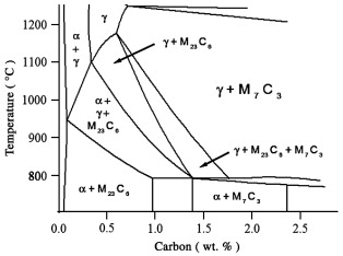
440C. Based on the pseudobinary phase diagram for a 17% chromium alloy, this steel appears to relatively uncomplicated, Fig. 3. When austenitized at 1050 °C, the likely primary constituents are austenite, M7C3 and M23C6. Quenching to room temperature, followed by double tempering at 550 °C for 2 + 2 h yields a martensitic microstructure containing these carbides and small amounts of retained austenite. These constituents are clearly revealed when the specimen is etched with the 1% modified metabisulfite color etch, Fig. 4a. The NaOH + KMnO4 etch, Table 3, number 5, appears to lightly etch all of the carbides and reveal a large amount of carbide banding in the rolling direction, Fig. 4b. Etching the steel with the electrolytic Ammonium Persulfate etch appears to darken the larger carbides slightly more than the smaller carbides, Fig. 4c. However, the etching of the individual large carbides appears to be uniform.
X-ray diffraction by chromium radiation from 20° ≤2θ ≤ 165.6° of the dissolved carbides from 440C reveals many peaks, Fig. 4d. The peaks are found to correspond to M7C3 and M23C6, ICDD cards 36-1482 and 5-721, respectively, Table 4. The M7C3 is reported to have an orthorhombic crystal structure. The ICDD lattice constants are a = 0.70149 nm, b = 1.2153 nm and c =0.4532 nm. The M23C6 carbide is reported to have a face centered cubic structure and a lattice parameter of a = 1.06228 nm. For this particular composition, the experimentally determined lattice parameters for the M7C3 carbides were found to be a = 0.69501 nm, b =1.22459 nm and c = 0.45160 nm. The lattice parameter of the M23C6 carbide was found to be a = 1.05849 nm. These values are in excellent agreement with the ICDD values. The diffraction peaks corresponding to the M7C3 carbide can be attributed to a hexagonal crystal lattice as well. In this instance, the corresponding ICDD, 5-720, lattice parameters are a = b = 1.398 nm and c =0.4523 nm. The experimentally determined lattice parameters for the M7C3 carbide were a = b = 1.39452 nm and c =0.45160 nm. Here again, the experimentally determined lattice parameters are in excellent agreement with those reported by ICDD. The orthorhombic–hexagonal relationship is discussed in detail in the International Tables for X-ray Crystallography [27].
Table 4.
440C; γ = 1050 °C 1 h, tempered 2 + 2 h at 525 °C; lattice parameters and crystal structures
| | M23C6 | M7C3 | M7C3 |
|---|
| FCC (nm) | Orthorhombic (nm) | Hexagonal (nm) |
|---|
| a | 1.05849 | 0.69501 | 1.39452 |
|---|
| b | | 1.22459 | |
|---|
| c | | 0.45126 | 0.45160 |
|---|
| d (nm) | I/I0 | | | |
| 0.60590 | 8 | (1 1 1) | (0 2 0) | (2 0 0) |
| 0.31812 | 2 | (3 1 1) | | |
| 0.26403 | 3 | (4 0 0) | (2 3 0) | (4 1 0) |
| 0.23623 | 22 | (4 2 0) | | (3 2 1) |
| 0.22828 | 7 | | (2 3 1) | (4 2 0) |
| 0.21573 | 27 | (4 2 2) | (0 5 1) | (1 1 2) |
| 0.21095 | 8 | | (1 1 2) | (2 0 2) |
| 0.20347 | 100 | (3 3 3) | (3 1 1) | |
| 0.20139 | 3 | | | (6 0 0) |
| 0.18692 | 20 | (4 4 0) | (2 1 2) | (3 1 2) |
| 0.18393 | 2 | | (3 3 1) | (6 0 1) |
| 0.18060 | 4 | | (2 2 2) | (4 0 2) |
| 0.17875 | 21 | (5 3 1) | | |
| 0.17626 | 11 | (6 0 0) | (2 6 0) | |
| 0.17451 | 3 | | (0 7 0) | (4 4 0) |
| 0.16723 | 3 | (6 2 0) | (4 2 0) | (6 2 0) |
| 0.16132 | 3 | (5 3 3) | (1 5 2) | (7 0 1) |
| 0.15947 | 8 | (6 2 2) | (4 3 0) | (7 1 0) |
| 0.14816 | 1 | (7 1 1) | (1 6 2) | |
| 0.14340 | 1 | | (4 4 1) | (8 0 1) |
| 0.13459 | 2 | | (2 2 3) | (6 2 2) |
| 0.13230 | 6 | (8 0 0) | (4 6 0) | (3 2 3) |
| 0.12835 | 9 | (8 2 0) | (2 7 2) | |
| 0.12475 | 34 | (6 6 0) | (1 8 2) | |
| 0.12223 | 22 | (5 5 5) | | |
| 0.12054 | 5 | | (3 3 3) | (6 0 3) |
| 0.11834 | 11 | (8 4 0) | (5 0 2) | (8 3 1) |
| 0.11621 | 19 | (7 5 3) | (5 2 2) | (6 6 0) |
| 0.11549 | 1 | (8 4 2) | | |
- Full-size table
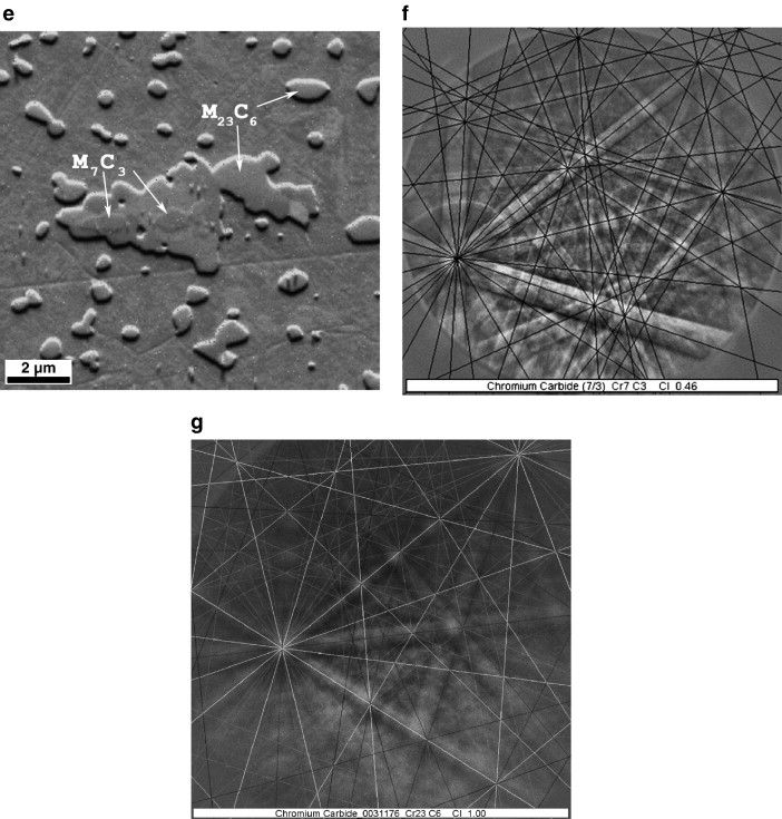
When examined at higher magnification in the SEM, some of the larger carbides appear to be composed of two discrete constituents, Fig. 4e. EBSD analysis indicated that the slightly darker constituent in the center of the larger carbides is M7C3, Fig. 4f, and the surrounding carbide is M23C6, Fig. 4g.
BG42. The microstructure of heat treated BG42 is found to consist of tempered martensite and many banded carbides, Fig. 5a. After using etch 5, Table 3, most of the carbides are found to be fairly uniformly attacked, Fig. 5b. Numerous large cracked carbides are noted in this alloy, Fig. 5a and b. Voids adjacent to large or banded carbides are observed, Fig. 5b. Using chromium radiation, and scanning from 20° ≤ 2θ ≤ 165.6°, approximately 27 peaks are observed, Fig. 5c. The vast majority of these peaks were found to correspond to the M23C6 carbide, ICDD 5-721. For this particular alloy composition and heat treating parameters, the lattice constant is a = 1.06386 nm which is quite similar to ICDD 5-721. EBSD analysis confirmed these results. In addition, numerous small carbides visible at higher magnification were found to be VC by EBSD analysis, Fig. 5d. The small VC carbides were isolated and in general not attached to the larger M23C6 carbides.
M50-Nil. The microstructure of M50-Nil in the quenched and tempered condition was found to consist of tempered martensite, a small amount of retained austenite and numerous small well dispersed carbides, Fig. 6a. The carbides were not etched or attacked when the 0.5% modified metabisulfite color etch was used, Fig. 6a. When etched with the NaOH + KMnO4 solution, Etch 5, Table 3, only the carbides are colored, Fig. 6b. The carbides are clearly observed and appear to be uniformly colored. The carbides in the case of M50-Nil are generally less than 1 μm in diameter. X-ray diffraction of the extracted carbides indicated that five of the six large peaks having relative intensities greater than 20% corresponded to VC or V7C8, Fig. 6c. Some of the less intense peaks could possibly be attributed to either Mo2C, or MoC. EBSD confirmed that the peaks from the small carbides that were able to be resolved with the SEM were VC, Fig. 6d.
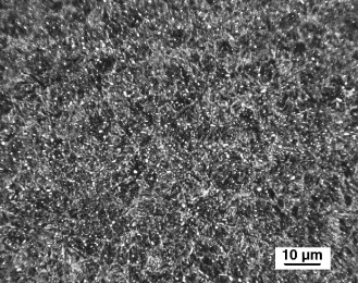
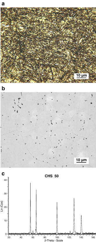
CHS 50. The microstructure of the easily carburizable M50 type of steel, CHS 50, was found to have a microstructure somewhat similar to M50-Nil. As revealed by using the 0.5% modified potassium metabisulfite etch, the primary constituents were tempered martensite, retained austenite and small well distributed carbides, Fig. 7a. When the alloy was etched with the NaOH + KMnO4 solution, Etch 5, Table 3, the carbides were found to generally be less than 1 μm in diameter, and the carbides appear to be outlined but not uniformly colored, Fig. 7b. This is contradictory to previously published results for this particular etch [17] and [18]. In this specimen, the carbides appear to be slightly larger than those observed in M50-Nil. The volume fraction of carbides in the CHS 50 alloy appears to be somewhat lower than the corresponding carbide volume fraction in M50-Nil. Prior austenite grain boundaries are faintly revealed by the NaOH + KMnO4 etch, Fig. 7b.
There is a great difference between the X-ray diffraction pattern for CHS 50, Fig. 7c as compared to M50-Nil, Fig. 6c. The peaks from the extracted carbides in CHS 50, Table 5, correspond quite well with ICCD card 15-457. This is for Mo2C having a face centered cubic lattice with a = 0.41550 nm. The highest 5 peaks for ICDD 15-457 occur at d-spacings of 0.238 nm, 0.207 nm, 0.147 nm, 0.126 nm, and 0.120 nm. For chromium radiation, the corresponding 2θ angles are 57.51°, 67.16°, 102.69° and 145.12°, respectively. The values for these peaks are in close agreement with the experimentally observed 2θ values of 56.30°, 66.01°, 100.73°, 129.20° and 141.26°. The relative intensities of the carbide peaks in CHS 50 were 100%, 88%, 66%, 76%, and 40%. The experimentally observed peak intensities are similar to those reported for ICDD 15-457, 100%, 80%, 70%, 70%, and 40%, respectively. Experimentally, the lattice parameter for the carbides in the carburized alloy was found to be a = 0.42037 nm. SEM–EDS analysis of the carbides indicates that they are composed of molybdenum and, to a lesser degree, vanadium. The approximate ratio of Mo:V in these carbides varies from 3:1 to 7:1.
Table 5.
Hardened CHS 50 carbides; lattice parameters and crystal structures
| Mo2C |
|---|
| FCC (nm) |
|---|
| a = 0.42037 |
|---|
| d (nm) | I/I0 | |
| 0.24267 | 100 | (1 1 1) |
| 0.21018 | 88 | (2 0 0) |
| 0.14866 | 66 | (2 2 0) |
| 0.12673 | 76 | (3 1 1) |
| 0.12135 | 40 | (2 2 2) |
- Full-size table
CHS 1. This alloy is based on the composition of M1 HSS; however, the chromium content of CHS 1 evaluated in this investigation was only 1.5%. In order to offset the decrease in hardness caused by lowering the chromium content to 1.5%, the molybdenum content was increased to 9%. The microstructure in the carburized case of this steel is composed of tempered martensite, a small amount of retained austenite and numerous carbides having lengths up to 10 μm, Fig. 8a. X-ray diffraction clearly indicates that the carbides in CHS 1 are M6C, Fig. 8b. Crystallographically, the carbides are FCC and have a lattice parameter of 1.10729 nm. This is in excellent agreement with ICCD 41-1351 that reports a lattice parameter of 1.11094 nm for the FCC M6C carbide.
M62. This high speed steel is generally produced by a powder metal route. Gas atomized powders are canned, hipped and then extruded or rolled into final product. The powder metal processing is used because of the alloy's high carbon and alloy content, Table 1. The heat treating procedures used for this alloy generally triple temper the material to transform any retained austenite to martensite. This heat treatment results in a microstructure that is essentially martensite and contains a high volume fraction of carbides. When etched with the modified metabisulfite color etch, the tempered martensite is dark and the carbides are not attacked or etched, Fig. 9a. The carbides are observed to have two distinct morphologies, rods and globular, Fig. 9a. X-ray diffraction of extracted carbides reveals two types of carbides. One type of carbide is M6C and the other is Mo2C, Fig. 9b. The M6C is FCC and has a lattice parameter of 1.10573 nm. The Mo2C is orthorhombic, with lattice parameters of a = 0.46844 nm, b = 0.59992 nm and c = 0.51200 nm. Using EBSD, the rod-like carbides are clearly shown to be the orthorhombic Mo2C, and the globular carbides are the M6C type, Fig. 9c. In this HSS, the rods and globular carbides are distinct particles. Unlike the case for 440C, one type of carbide does not serve as a nucleation site for the other type of carbide.
P675. A modified metabisulfite etch clearly reveals that, when carburized, this alloy has a surface layer consisting of tempered martensite and numerous alloy carbides, Fig. 10a. Etching with the NaOH + KMnO4 solution reveals numerous small carbides in the carburized layer, Fig. 10b. Within the outer layer of the carburized material, the carbides are seen to have either a rod-like or small globular morphology, Fig. 10c. EBSD analysis indicates that the globular carbides are M23C6 while the rod carbides are M7C3, Fig. 10c. In some instances, the globular carbides appear attached to the rods. This is similar to what was observed in 440C, Fig. 4e. Near the carburized surface, there appears to be a higher volume fraction of the rod-like carbides compared to regions farther below the surface.
CSS-42L™. The microstructure of this carburizing steel is somewhat more complex than P675. After carburizing and heat treating, three distinct regions are observed in the microstructure, Fig. 11a. The intermediate zone between the carburized case and the core is found to be entirely austenitic, Fig. 11b. When etched with the modified metabisulfite etch, the surface layer of the alloy consists of tempered martensite and a large volume fraction of carbides, Fig. 11c. Etching with the NaOH + KMnO4 solution darkens but does not attack the M23C6 carbides, Fig. 11d. EBSD analysis of the carbides near the surface, as well as those below the surface, indicated that all were M23C6. No M7C3 carbides were observed in this specimen.
4. Discussion
The results from this investigation indicate that several complex transformations occur in these steels during processing. In particular, the specific carbides and their morphologies depend on the alloy composition as well as the processing used to achieve the final structures. In addition, some confusion regarding the crystallography of some of the carbide phases reported in the literature needs to be considered.
440C and BG42. Both of these alloys contain 1% carbon and 17% Cr. Based on the 17% Cr Isopleth from the Fe–Cr–C phase diagram, the equilibrium phases predicted to exist at the austenitizing temperature of 1050 °C are γ and M7C3, Fig. 3. However, both the X-ray diffraction data and the EBSD analysis indicate the constituents in the alloy after tempering and hardening are tempered martensite, M23C6 and M7C3. As indicated by the phase diagram, at the austenitizing temperature, this particular composition is very close to the boundary between γ + M7C3 and γ + M7C3 + M23C6. Thus some M23C6 may be present during austenitizing. Furthermore, considering the mill processing received by this alloy prior to austenitizing in the laboratory, it is quite likely that M23C6 was in the microstructure. In addition, nonequilibrium solidification could result in the presence of M23C6 at elevated temperatures. The EBSD analysis indicated that, inside the large carbides, a slightly darker constituent was observed. The darker interior regions of the carbides are M7C3, Fig. 4f, and the surrounding carbide is M23C6, Fig. 4g. In other cases, the small individual carbides are generally M23C6. This material has been cast into ingots and rolled and reheated several times. However, considering the relatively slow rates of diffusion of chromium in austenite, it is most likely that the M7C3 precipitated from the liquid steel. Then as solidification proceeded, the M23C6 nucleated on the M7C3 carbide and grew larger.
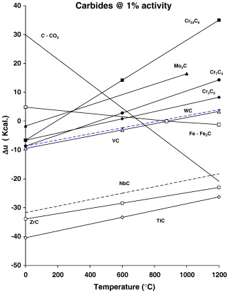
Based on chemistry, BG42 appears to be a more complicated alloy than 440C. However, both X-ray and EBSD analysis indicates the majority of the carbides present are M23C6, Fig. 5c. Upon closer evaluation, some very small carbides are seen to be uniformly distributed in the microstructure of the material, Fig. 5d. EBSD analysis indicated that these carbides are VC. This is not too surprising considering that the steel contains approximately 1.2% vanadium. Based on available thermodynamic information [28], it is quite likely that the VC forms in the liquid or just after solidification of the alloy. This is because, compared to the other carbide forming elements in the steel, VC has a much more negative free energy of formation than carbides of chromium or molybdenum, Fig. 12.
Carburizable HSS alloys. After heat treating, in the carburized case, M50-Nil has a hardness in excess of 60 HRC. This high hardness is the result of the combination of a high carbon content, alloying and the secondary hardening phenomena caused by the precipitation of M2C when the steel is tempered in the range of 500 °C. As the X-ray diffraction pattern and the EBSD analysis indicates, the major carbide observed is VC, Fig. 6c and d. The presence of this carbide is due to its high free energy of formation compared to other alloy carbides. Some of the VC forms during solidification, and the remainder forms during carburizing and subsequent heat treating. The VC that forms during the initial processing of the steel and during carburizing is most likely that which is observed by optical metallography, Fig. 6b. In addition, Mo2C forms during tempering. However, since this carbide is of nanoscale proportions, it can only be resolved by transmission electron microscopy. Crystallographically, in M50-Nil and other alloys, this carbide has been reported to have a hexagonal structure [29] and [30].
In contrast to M50-Nil, the easily carburizable alloy CHS 50 has a reduced chromium level and a higher molybdenum content, Table 1. While this steel contains approximately 1% vanadium, the large carbides that are observed by optical microscopy are Mo2C rather than VC. While these carbides do contain some vanadium, the principal constituent is molybdenum. Furthermore, crystallographically, in this alloy the Mo2C has a FCC structure and a lattice parameter of a = 0.42037 nm. This lattice parameter is in excellent agreement with that reported for ICDD card 15-457, Table 2. The most likely reason for forming the cubic version of the Mo carbide is probably due to the reduced levels of chromium in the easily carburizable alloys, 1%, as compared to M50-Nil that contains approximately 4% chromium. The presence of this carbide, as compared to the hexagonal morphology, may be a contributing factor to the excellent hardness and hot hardness displayed by this alloy.
Carburizable 14% Cr alloys. Both P675 and CSS-42L™ are high chromium carburizing steels. Besides containing a high amount of chromium, both of these steels contain nickel and cobalt. CSS-42L™ contains a greater amount of each element compared to P675, Table 1. Both of these elements tend to enlarge the austenite field of the steels at elevated temperature. To fully understand the nature of the carbides formed in these steels, an Isopleth at 14% Cr from the Fe–Cr–C phase diagram can be of assistance [31], Fig. 13. After being fully annealed, these alloys contain approximately 0.1% carbon. The phases present are alpha iron and a small amount of M23C6; as previously discussed a very small amount of VC may be present, Fig. 12.
For P675, since the carbon content of the steel decreases as the depth below the surface increases, the M7C3 carbide forms at high carbon levels, and the M23C6 carbide forms at lower carbon levels. In addition, this possibly suggests that the M7C3 carbides serve as nucleating agents for the M23C6. After vacuum carburizing, the steel may have a surface carbon content in excess of 1%. For a standard carburizing temperature of approximately 950 °C, the equilibrium phases predicted by the Fe–Cr–C Isopleth for an alloy containing 14% Cr would be γ + M7C3, Fig. 13 (it should be noted, that this is an approximation. The presence of cobalt and nickel in the steel will obviously change the exact boundaries of the phase fields). Based on EBSD analysis, the M7C3 is found to have a rod morphology, Fig. 10c. Since the initial carbon content of the alloy is approximately 0.07%, various amounts of γ, and M23C6 would be expected to be present at 950 °C. During the diffusion cycle, since the temperature is constant as time increases, carbon would be expected to diffuse from the surface of the specimen in to the core, thus lowering the carbon content of the near surface material. As this occurs, according to the phase diagram, the amount of M7C3 would be expected to decrease while the amount of M23C6 should increase. The mechanism for this is illustrated by Fig. 10c. As the diffusion cycle continues, the carbon content decreases and the M7C3 appears to transform from rods to globular M23C6, Fig. 10c. The EBSD analysis and the SEM micrographs indicate the transformation begins on the thin side of the carbide rods and not along the length of the rods.
For carburized CSS-42L™, the cobalt and nickel contents are much higher than for P675. Thus it would be expected that a larger deviation in the position of the various phase boundaries in the 14% Cr Isopleth might occur for this alloy at elevated temperatures. For the specimen evaluated in this study, only M23C6 carbides were found in the carburized case, Fig. 11. This could be due to several different reasons. First, the carburizing potential of the heat treatment for this alloy may have been lower than that used for the P675 specimen. Second and more likely is that due to the higher alloy content in CSS-42L™, little or no M7C3 was formed during the carburizing cycle, or none remained after the diffusion cycle.
Crystallography of M7C3. Based on the ICCD data files, there appears to be some confusion regarding the crystallography of M7C3. As cited in Table 2, various reports include the following: (Cr,Fe)7C3, 5-720, hexagonal; Cr7C3, 11-550, hexagonal, and Fe7C3, 17-333, hexagonal. One of the most recent reports, 36-1249, lists Cr7C3 as orthorhombic. In actuality, either crystal structure may be used to describe M7C3. That is because there is a mathematical relationship between the two symmetry groups [27]. For example ICCD 36-1482 lists the lattice parameters for Cr7C3 orthorhombic cell when evaluated with copper radiation as a = 0.70149 nm, b = 1.2153 nm and c = 0.4532 nm. Using the ICDD data and the WIN Metric software, at a tolerance of 0.8° (2θ degrees), the calculated lattice parameters are a = 0.70149 nm, b = 1.21543 nm and c = 0.45314 nm. These values are in quite good agreement with those reported by ICDD. For the present analysis all the reported lines were found to fit the reported lattice parameter. As the tolerance for the unit cell was reduced from 0.8° to 0.1°, all the lines observed in the diffraction pattern were still in agreement with the original unit cell. When the analysis was performed for a hexagonal unit cell, the lattice parameters were found to be a = b =1.40330 nm and c = 0.45314 nm. This analysis indicates that the two unit cells share a common c axis, and that the a and b axes of the hexagonal are approximately twice as long as the a axis of the orthorhombic cell. As the tolerance for the unit cell is decreased from 0.8 to 0.6, 0.4, 0.2 and 0.1, the number of lines not correctly indexed increases from 1 to 3, 3, 11 and finally 17. This indicates that the ICDD data for 36-1482 fits an orthorhombic unit cell better than the hexagonal unit cell.
For the M7C3 found in the 440C austenitized at 1050 °C, the diffraction pattern can be represented by either an orthorhombic or hexagonal unit cell. The lattice parameters for the orthorhombic crystal with a tolerance of 0.8 are a = 0.695986 nm, b = 1.22795 nm and c = 0.449935 nm. At a tolerance of 0.8, one line in the diffraction pattern does not appear to correspond to the orthorhombic lattice. As the tolerance is reduced to 0.6, 0.4, 0.2 and 0.1, the number of lines appearing not to be indexed increases from 2, to 4 to 10 and then 13. Small changes in the lattice parameters result as the tolerances are reduced. Similarly, for a tolerance of 0.8, the hexagonal crystal has lattice parameters of a = b =1.39529 nm and c = 4.52067 nm and three lines are not properly indexed. As the tolerance for the hexagonal lattice is reduced to 0.6, 0.4, 0.2 and 0.1, 5, 9, 13, and 17 lines appear not to be indexed.
There are two types of carbides in 440C, M23C6 and M7C3. To properly index the pattern for 440C, the M23C6 carbide needs to be considered. When the M23C6 carbide is considered, 20 of the 29 lines in the diffraction pattern correspond to this carbide having a FCC lattice and a = b = c = 1.05849 nm at tolerances as low as 0.2. Selecting a tolerance of 0.4 for M7C3 having an orthorhombic lattice allows all but two lines in the diffraction pattern to be properly indexed. The corresponding lattice parameters are a = 0.695008 nm, b = 1.224259 nm, and c = 0.451256 nm. Similarly for the hexagonal lattice and a tolerance of 0.4, the corresponding lattice parameters are a = b = 1.39452 nm and c = 0.451603 nm. For the tolerance of 0.4, three lines in the pattern are not properly indexed. In 440C and other commercial alloys, the carbides are generally referred to as MxCy. This is because unlike ICDD for Cr7C3, in commercial steel, the chromium may be replaced to a certain degree by iron. In addition other residual elements such as molybdenum, vanadium and tungsten may be contained in the alloy carbides. Thus, while very exact computer analysis of the total diffraction pattern seems to suggest the best fit for the M7C3 is the orthorhombic lattice, the hexagonal lattice is probably just as good a fit considering the carbides are not a chemically pure species. Thus the lattice parameters for a tolerance of 0.4 can both be used equally well to represent the M7C3 analyzed in this study, Table 4.
Metallography of the Carbides. The color etch used in this study to reveal the general microstructure was a modified metabisulfite solution. This etch clearly colors the martensite in the steels while leaving the austenite unetched, or only lightly etched. Since this etch does not attack or color any of the carbides, they appear as bright white constituents in the microstructure, Figs. 4a, 5a, 6a, 8a, 9a and 11c. Slight over etching helps to accentuate the white carbides.
As revealed by X-ray diffraction and the EBSD analysis, 440C contains two types of carbides, M23C6 and M7C3. Another point of interest is the response of these two types of carbides to different etches. The modified metabisulfite etch darkens the steel matrix while leaving all the carbides unetched or attacked. In this condition the carbides appear white. Careful observation accompanied by changing the focus plane does not reveal any noticeable differences in the carbides. Similarly, using polarized light and rotating the specimen does not cause any of them to become lighter or darker than observed in white light. The other etches in Table 3 appear to successfully etch or outline both M23C6 and M7C3, but they do not allow the two different crystallographic species to be identified, Fig. 4b and c. The secondary SEM micrograph reveals two different gray levels in the large carbides. The combination of the secondary image and the EBSD analysis clearly reveals the two different species. These results are contrary to what has been previously reported [17] and [18]. Etch 5 claims to attack (Fe,Cr)23C6 and not attack (Fe,Mo)23C6. As indicated in Fig. 4b and c, both etches appeared to uniformly etch the large carbides that are either M7C3 or M7C3 surrounded by M23C6. Since the alloy contains approximately 0.75% Mo, this element would likely be expected to be in both the M23C6 and the M7C3 carbides. In both situations, the very small carbides appear to only be outlined.
For BG42, the metabisulfite etch clearly does not etch the carbides and they appear bright white after the matrix is etched, Fig. 5a. Similarly, Etch 5 darkens both the small and large carbides, Fig. 5b. Similar results were found for Etch 6.
Etch 5 was found to clearly reveal the small carbides in the carburizable M50-Nil and CHS 50 alloys, Fig. 6 and Fig. 7. The carbides observed in M50-Nil are primarily VC and appear to be darkened by Etch 5. However, the carbides in CHS 50 are (Mo,V)C and are outlined by Etch 5. Similar results were found for Etch 6. The primary carbides in CHS 1 are not attacked or etched by the metabisulfite etch. As confirmed by X-ray diffraction, they are primarily M6C and appear bright white, Fig. 8a.
X-ray diffraction analysis of the carbides in M62 indicates that both M6C and Mo2C are present. The EBSD analysis indicates that the M6C carbides are round, and the Mo2C carbides are rod-like, Fig. 9c. The two morphologies are clearly revealed when the metabisulfite etch is used, Fig. 9a. However, Etches 1 through 6 do not seem to etch, outline or attack the Mo2C. The alkaline sodium picrate etch, Etch 1, Table 3 appears to easily etch the M6C carbides. However, the rod-like Mo2C remains unetched, Fig. 14a. Using Murakami's etch, #2, Table 3 for 2 min appears to overetch the specimen, Fig. 14b. Lightly repolishing with 0.05 mm Al2O3 for 10 s removes the etching of the matrix, Fig. 14c. Unfortunately, only the M6C carbides appear to be etched. The Mo2C remains unetched. Similarly electrolytic CrO3 etches the M6C but does not etch or outline the Mo2C, Fig. 14d. Increasing the etching time with the electrolytic CrO3 solution only serves to over etch the matrix of the steel, Fig. 14e. The M6C and Mo2C carbides are not outlined or etched by the H2O2 + NaOH solution, Etch 4, Table 3. The NaOH + KMnO4 solution, Etch 5, appears to only darken the M6C carbides while leaving the Mo2C unattacked, Fig. 14f. Similar results are obtained with Etch 6, Fig. 14g.
These results show the etches commonly recommended for revealing specific carbide types in general do not consistently work for various high alloy steels. The modified metabisulfite etch will easily darken the tempered martensitic matrix of most high alloy steels, and leave all the carbides unetched. Thus the carbides can be easily observed by optical microscopy at high magnification. As indicated, it was not possible to distinguish M7C3 from M23C6 in the high chromium steels. Similarly, it was not possible to selectively etch Mo2C with any of the conventional carbide etches in M62 HSS. X-ray diffraction of the extracted carbides can assist in determining the crystallography of all the carbides in these alloys present in a significant volume fraction. However, for an accurate analysis of the carbide and their morphology, EBSD appears to be the best technique.
5. Conclusions
- 1.
The primary type of carbide found in the easily carburizable low chromium CHS 50 steel was Mo2C having a face centered cubic crystal structure. This is significantly different from the hexagonal Mo2C reported for other high alloy steels containing higher levels of chromium.
- 2.
X-ray diffraction of the large carbides extracted from steels can be used to determine their crystallography. However, to properly describe the carbides, EBSD provides information relating to both crystallography and morphology. As discussed, observing the transformation of M7C3 to M23C6 was only possible with EBSD.
- 3.
EBSD can be used to provide information regarding the crystallography of constituents present in relative low volume fractions.
- 4.
The commonly used carbide etches do not seem to properly differentiate or, in some cases, etch the carbides present in the high alloy steels used in this study.
Acknowledgements
The authors wish to express their thanks to The Timken Company for permission to publish this paper. The efforts of Michelle Petraroli in specimen preparation and David Wolf in carbide extraction are greatly appreciated. The assistance provided by Andy Fisher of Ametek and Matt Nowell of EDAX/TSL in obtaining high quality EBSD patterns and correctly indexing them is appreciated. The assistance of Bob Gold of Westinghouse Science and Technology, is appreciated for providing some of the thermodynamic data.
References
- [3]
- K.H. Jack
Structural transformations in the tempering of high carbon martensitic steel
JISI, 169 (1951), pp. 26–36
- [SD-008]
- [4]
- Y. Hirotsu, S. Nagakura
Crystal structure and morphology of the carbide precipitation from martensite high carbon steel during the first stage of tempering
Acta Met, 20 (1972), pp. 645–655
- [SD-008]
- [5]
- J.M. Beswick
The effect of prior cold work on the martensite transformation in 52100 steel
Met Trans A, 15A (2) (Feb. 1984), pp. 299–306
- [SD-008]
- [6]
- The International Centre for Diffraction Data, Powder Diffraction Data, Newton Square, PA.
- [SD-008]
- [7]
- Boehm HH, Gang DH. Unpublished. Timken Research, ca 1967.
- [SD-008]
- [8]
Metals handbook, Metallography, Structure and Phase Diagrams (8th Ed.), vol. 8, ASM, Metals Park, OH (1973), p. 404
- [SD-008]
- [9]
- H.J. Goldschmidt
The structure of carbides in alloy steels, part I — general survey
JISI (Dec. 1948), pp. 345–362
- [SD-008]
- [10]
- H.J. Goldschmidt
The structure of carbides in alloy steels, part II — carbide formation in high speed steels
JISI (March 1952), pp. 189–204
- [SD-008]
- [11]
- D.J. Blickwede, M. Cohen, G.A. Roberts
The effect of vanadium on the constitution of high speed steel
TASM, 142 (1950), pp. 1161–1191
- [SD-008]
- [12]
- D.J. Blickwede, M. Cohen
The isolation of carbides from high speed steel
Met Trans., 185 (1949), pp. 578–584
- [SD-008]
- [14]
- W. Crafts, J.L. Lamont
Secondary hardening of tempered martensitic alloy steel
Trans AIME, 180 (1949), pp. 471–512
- [SD-008]
- [15]
- J.E. Bridge, G.N. Manir, T.V. Philip
Carbides in M-50 high speed steel
Met Trans, 2 (Aug. 1971), pp. 2209–2214
- [SD-008]
- [17]
- G.F. VanderVoort, E.P. Manilova, J.R. Michael
A study of selective etching of carbides in steel
Microsc Microstruct Anal, 10 (Suppl 2) (2004), pp. 76–77
- [SD-008]
- [18]
- VanderVoort, G.F., Metals Handbook, 9th Ed., Vol. 9.
- [SD-008]
- [19]
- J.R. Michael, R.P. Goehner
crystallographic phase identification in the scanning electron microscope: backscattered electron Kikuchi patterns imaged with a CCD-based detector
MSA Bull, 23 (1993), p. 168
- [SD-008]
- [20]
- US Patent #4,659,241.
- [SD-008]
- [21]
- US Patent #6,702,981.
- [SD-008]
- [22]
- D.W. Hetzner
Carburizable high speed steel alloys
,in: J.M. Beswick (Ed.), Bearing Steel Technology, ASTM, STP, vol. 419, American Society for Testing and Materials, West Conshohocken, PA (2001)
- [SD-008]
- [23]
- D.W. Hetzner
Continued developments in easily carburizable high speed steel alloys
J. ASTM Int., 3 (2) (Feb. 2006)
- [SD-008]
- [24]
- US Patent #5,002,729.
- [SD-008]
- [25]
- US Patent #5,424,028.
- [SD-008]
- [27]
International tables for X-ray crystallography
Symmetry Groups, vol. IThe International Union of Crystallography, Birmingham, England (1962)
- [SD-008]
- [28]
- F.D. Richardson
The thermodynamics of metallurgical carbides and of carbon in iron
JISI, 175 (Sept. 1953), pp. 33–51
- [SD-008]
- [29]
- S.G. Song, H. Du, E.Y. Sun
Lattice orientation relationships between the M2C carbide and the ferrite matrix in the M50-Nil bearing steel
Met Trans, 33A (7) (2002), pp. 1963–1969
- [SD-008]
- [30]
- J.S. Montgomery, G.B. Olson
Kinematics of M2C Carbide Precipitation
Innovations in ultrahigh-strength steel technology, Proc. 34th Sagamore Conf., Lake George, NY, U. S. Army Lab. Comm., MTL, Adelphi, MD (1987), pp. 89–111
- [SD-008]
- [31]
- Madeleine Durand-Charre, The Microstructure of Steels and Cast Irons, Ed. Springer, Chapter 4, p. 51–73.
- [SD-008]
Copyright © 2007 Elsevier Inc. All rights reserved.


")